What actually a Breadboard is ????
1. Its a construction base for prototyping electronics circuit & models
2. In breadboard the circuits are temporary arranged for testing purpose
3. Its simply a solder-less board , you don't need to solder the electronics component
4. In this tutorial we will learn how to use a breadboard
 |
fig.1 - This is how a actual breadboard look like
|
Now lets start our tutorial , first of all collect the following items at your work space along with your
breadboard
1. Hook wire :- You can easily get this wire in electronics shops around you, we will use this wire for
bread board connections
 |
fig.2-hook up wires
|
2. Wire stripper :- In a simple way a stripper is a sort of wire cutter it is used to strip the insulating
plastic of the hook wire with a perfection & ease
 |
fig.3-wire stripper
|
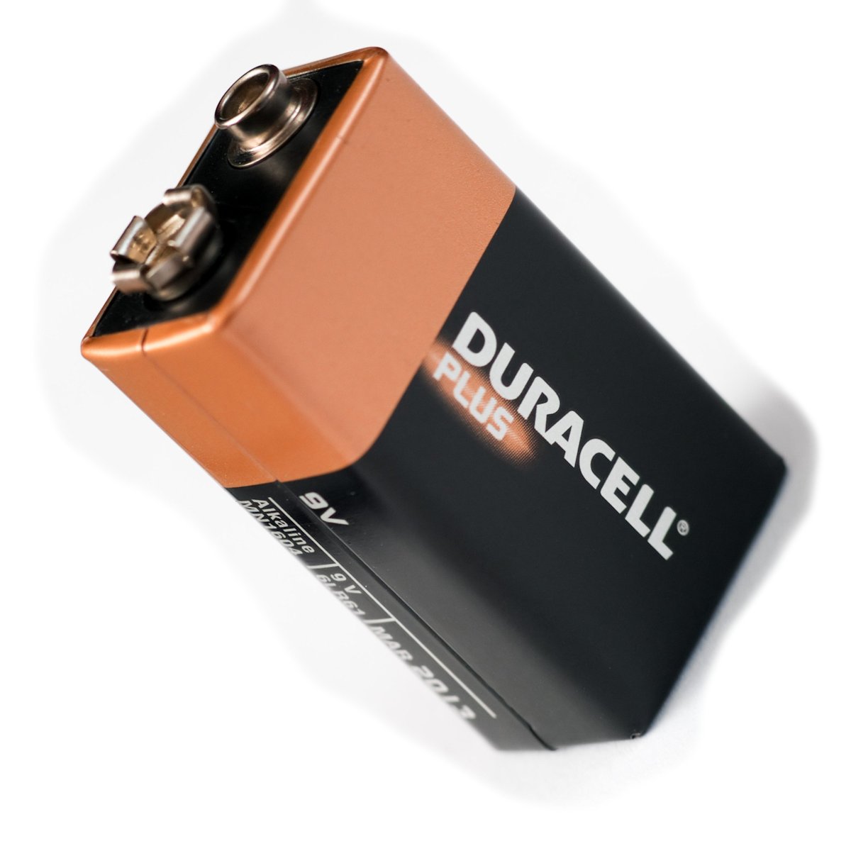
3. Battery, 9v :- A 9 volt battery for power supply of breadboard
 |
fig.4- 9 volt battery
|
4. Battery cap :- Its basically a connector for standard size 9v battery with two wires
red wire - v cc
black wire- ground
 |
fig.5- battery cap
|
5.Miscellaneous:- some basic electronics component like Led's , IC, in this tutorial we will learn how to
do breadboard connections step by step and some basic concept of electronics
collect all the Items at your work station
This is our bread board let us explore it from inside that how the connections and arrangement is
done inside the bread board
We can understand it with the help of diagram given below
so here we can see that here are two railings of blue & red color on both side they are meant
for power supply of the bread board the outer most railing is take as a positive & inner most railing
take as negative (for our ease as in diagram it is given different)
we consider red as positive & black wire as negative
so let's start the connection
Step 1.
Arrange and hook the wire as given below the image for supply power to the whole breadboard
followed by this connection here we can see we have connected two more connection in between the breadboard as in breadboard after five block of power railing there is a break to join this break we connect this arrangement like this

Step:2 Check the electronic component with the help of multimeter
- we can check that our LED is working fine or not
- value of resistence
- voltage of battery
- continuity of circuit
Step-3 :- Try this circuit diagram on bread board
- you can take help from the below image if you want either do it with yourself
step 4:- This is how we have to connect the battery and battery cap
step 5: -Try this circuit diagram on bread board
step 6: - Just like that try led in series put 3 Led in series without Resistance
so this is the tutorial for breadboard hope it will help you
(Note:- led need needs only 2 to 2.5 volt for switching , so always connect a single Led with 1 k resistance ,as 9 v will damage LED if connected without resistance )
Project:-
Now let us make a project of simple torch light with 12 LED it consists of both series and parallel connection
- The circuit diagram is given below
- I have made it on dotted PCB you can try it own your bread board after that implement it on dotted PCB
Hope you like it all , in next basic electronics post I will explain about touch sensor
post your comment and subscribe me , Happy DIY